Radiology Continuing Education Series
Course 2 of 6
Choosing the Appropriate Exposure Factors
Course 1 – Physics of Radiology
Course 2 – Choosing the Appropriate Exposure Factors
Course 3 – Recording the Image
Course 4 – Poor Quality Films-Causes and Corrections
Course 5 – Radiation Safety-Importance and Procedures
Course 6 – Pros and Cons of Digital Radiography-CR vs. DR
A number of faults can occur that are detrimental to the diagnostic value of a radiograph, which is why it is important to  understand the exposure factors that affect radiograph quality. The most common cause of poor contrast in radiographs is inappropriate exposure factors. Through quality assurance and equipment care, these faults can be avoided, or rectified quickly preventing unnecessary repeat radiographs and extended anesthesia for the patient.
In the previous issue “Physics of Radiology” we discussed that kVp (kilovolt peak/kilovolt potential) gives variable “speed” to the electrons determining the penetration of the x-ray beam, which affects the efficiency of x-ray production, and determines the scale of contrast in the image. The mAs (milliampere seconds) determines the number of x-rays produced per unit time and the number of x-rays reaching the film determines the degree of blackening of the film.
In order to take a quality radiograph that details as much diagnostic information as possible the following factors must be considered:
• The type of tissue in the region of interest
• The type of x-ray machine (specifically the type of
generator)
• The type of film or screen system being used.
 The type of tissue in the region of interest constitutes the subject contrast which is what you want to display. For example, you want to display the differences between the bone cortex, the bone marrow cavity and the surrounding muscle; or display the difference between the liver, the falciform fat, the intestinal wall and the intestinal lumen; or display the difference between the air filled region of the lung, the pulmonary vessels and the heart. The major way to depict these is in the selection of the kVp used to image the area of interest.
The correct kVp will produce differential x-ray absorption of soft and dense anatomic structures. Increasing kVp increases the penetrating power of the x-ray beam. If kVp is too low, the image will lack density resulting in a whitewashed or sooty appearance. If kVp is too high the image will be over exposed and too dark.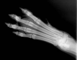
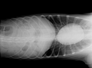
In small animals and in the distal extremity region of large animals where bone is the major structure of interest, a relatively low kVp (60-70) is sufficient to penetrate the bone and soft tissue. The low kVp will be very effectively absorbed by the bone mineral and provide good contrast. This level of kVp will provide a rather “contrasty” image which most find pleasing to use for bone evaluation. To provide the film blackening needed relatively high mAs will be needed. As always try to use the shortest time possible to prevent blurring from patient motion.
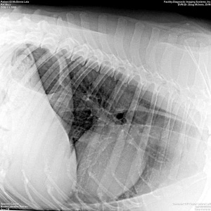 In the thorax where there is a large variation in the types of tissue present, thin pulmonary vessels, thick volume of the heart, very minimally absorbing aerated portion of the lung, a relatively high kVp (80-100) is desirable to distinguish this variety of subject contrast. As these x-rays will be quite energetic, not as many are needed to establish the degree of blackening so a relatively low mAs is used. A short exposure time is essential in the thoracic region to stop the blur of respiration motion.
The abdomen is more like the thorax region than the skeletal region when it comes to choosing your exposure factors. There are three major tissue types in the abdomen, soft tissue, fat and gas. However the individual organs vary significantly in thickness. A medium kVp (70-90) is desirable coupled with relatively low mAs. Although respiratory motion is not as great of a problem, it is still best to keep the exposure time as short as possible.
Preferred Relative Exposures: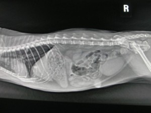
• Skeletal – High mAs with low kVp
• Abdomen – Medium mAs with medium
kVp
• Thorax – Low mAs with high kVp
 The best way to create predictably good images in veterinary radiography is to create and use a technique chart that is particular to each body area. The technique chart is based on standardization of as many different variables as possible and only changing one component of the exposure factors based on the thickness of the body area. To create this technique chart initially involves a trial and error process. Once the ideal exposure factors have been established for the desired area on your trial patient, there are simple mathematical relationships that can be used to fill in the chart for any other thickness of that body area.
To Be Standardized Are:
1. X-Ray tube to film distance
2. Collimator
3. Use of grid or no grid
4. X-ray film intensifying screen combination
5. Film processing
6. Darkroom lighting
X-Ray Tube to Film Focal Distance: This is a very simple relationship. The closer the x-ray tube is to the film the greater is 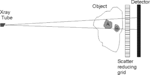 the intensity of the radiation exposure to the film. So by altering the x-ray tube to film distance you can effectively increase or decrease the blackening of the film. It is best to standardize this and is easiest to standardize this with a x-ray machine that has the tube mounted on a stand that is fixed to the table and film holder. This is the typical use in small animal radiography. If the tube is manually positioned each time and several different personnel are making images you need to use a measuring device to try to standardize the distance. Variations in film blackening are often noted when multiple personnel hand position the tube as everyone stands at just a little bit different distance from the patient. The relationship of x-ray intensity to distance is relatively profound – Intensity (1) = 1/d2, where d is the distance from the x-ray tube to the film. So you can see that if you double the distance, you reduce the radiation intensity to 1/4th, most small animal radiography is done at a fixed tube-film distance of 40 inches (100 cm). Large animal skeletal radiography is often done with 30 inches (75 cm).
 Collimator: The collimator is a device used to restrict the x-ray exposure to a specified surface area of the body. Its major result, relative to image quality, is that it significantly reduces the scattered radiation produced by the patient and this improves image contrast. It also serves two major radiation safety purposes, to reduce the exposure to the patient and to reduce the scattered radiation exposure to the animal holders if manual restraint is required. Collimators are available either as various diameter exchangeable cones or as an adjustable permanent attachment to the x-ray tube housing, the cone type collimators must be removed and exchanged with a different diameter to achieve a change in x-ray field size. The adjustable collimator also usually has a light associated with it that shows the field size on the patient. The light field type collimator greatly improves the ability to accurately position the x-ray beam to the area of interest on the patient.
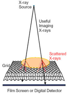
Use of a Grid or No Grid: A grid is a plate that consists of parallel spaced bars of lead. Lead is a very effectively absorber of x-rays. The purpose of the grid is to absorb scattered x-rays between the patient and the film. The scattered x-rays are created within the patient by an x-ray tissue interaction that results in the conversion of the incoming x-ray to an electron and a new x-ray with somewhat less energy moving in a new direction. In essence the x-ray is deflected off its original straight line course. If this redirected new x-ray successfully exits the patient it delivers exposure to the film that is untrue relative to the anatomical structure from which it originated.
Most grids are focused grids. This means that the lead bars are angled in the same plane as the x-rays coming from the tube. The grid is placed between the patient and the film. Most often in small animal systems the grid is incorporated into the table positioned just above the film tray. Grids can also be purchased that are laid on top of or independently affixed to the cassette. Grids are quite effective in removing the scattered x-rays from the image. Removal of the scattered x-rays improves the contrast in the image. Grids are generally used for area thickness greater than 10 cm. However, if you decide to use a grid for the area in question it may be easier to use it for all thicknesses rather than to have to remember to activate it or deactivate it.
Making a Technique Chart: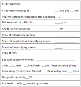
Now that you have standardized as many factors as you can you are ready to do some trial exposures, looking for the best for the area of interest. Before you begin make sure your x-ray machine is in good working order and the settings for kVp, mA and seconds are properly calibrated. If you are unsure whether your equipment is reliably calibrated, arrange a visit from a licensed service technician before proceeding.
You can make charts that are variable kVp or variable mAs or those that are a combination. Which type you make depends somewhat on the type of machine that you have to use. If you are using a fixed kV, fixed mA, but variable time machine (like many of the smaller portable machines) then your chart will by default be a variable mA chart. If your machine has mAs
and kVp selector controls or if
it has independent mA, time
and kVp selectors then you
could make either type of a chart.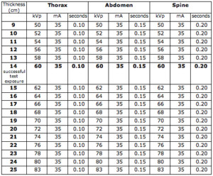
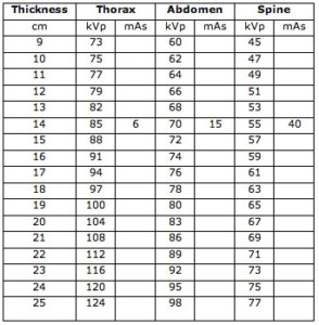
The basis for making a chart is to make several trail exposures until you find one that works best for that area in your trial patient. You then apply some mathematical relations to construct the selection factors for different sizes of that area. For an example, if you were to make a variable kVp chart for the canine abdomen you would make three trial exposures of the area with the dog lying in lateral recumbence. Measure the thickness of the trial patient and record it in cm. Because of the tissues within the abdomen use a fairly high kVp with relatively low mAs. Keep exposure time short to do away with respiratory motion effects on the cranial organs. Pick three exposure settings: first, 300 mA for 1/60 sec (5 mAs) at 70 kVp; second, 300 mA at 1/120 sec (2.5 mAs) at 70 kVp; and third, 300 mA at 1/30 sec (10 mAs) at 70 kVp. One has double the mAs and one has half the mAs. Using good collimation for the abdominal region, expose the three films and process them using standard processing technique. When the images are viewed hopefully one will be of good quality, with adequate background blackness (room air space around the patient) and good contrast scale for the abdomen. One should also be underexposed (overall too white) and one should be overexposed (overall too black). If none of the three are acceptable, repeat the test exposure modifying from the one that came the closest to what you want the image to look like. If you must repeat a second set of trial exposures you could modify any of the exposure factors, however it is preferable to alter the mA or exposure time. To correct underexposure, add 10 per cent to the kVp setting used or double the exposure time. To correct overexposure, subtract 10 per cent from the kVp setting used or halve the exposure time used.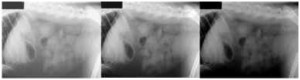
Once you have found the optimal or best set of exposure factors for the trial dog’s lateral abdomen you are ready to fill in the working chart for other thicknesses. There is a fairly linear relationship between kVp, area thickness,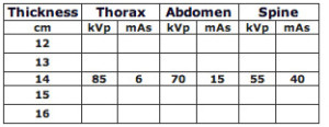 and response of the film-screen system.
• In the range of kVp less than 80 a change of two
kVp for each cm change in thickness will maintain
a quality image.
• Between 80-100 kVp the change is three kVp for
each cm change in thickness.
• For kVp greater than 100 the change must be four
kVp for every cm change.
This allows you to make a variable kVp chart for the abdomen. You would try this out on the same dog by taking the ventrodorsal (VD) view. Measure the abdomen, look up the kVp calculated for that thickness on your working chart and try it out. You would then repeat this process for every body area that you anticipate will need to be looked at radiographically. Most small animal charts contain factors for head, spine, thorax, abdomen, pelvis/hip joints, shoulder, and elbow/stifle/bones distal to elbow and stifle. Most equine charts have different settings for a region and for a specific view within that region. For example the equine foot requires increased exposure factors to emphasize the navicular bone versus the thin solar margin of the third phalanx.
As you repeat the trial process for each body region some general guidelines for modifying the general chart include:
• Low kVp settings with concurrent high mAs
settings give the best contrast for the skeletal
regions.
• High kVp setting with concurrent low mAs settings
give the best scale of contrast for the thorax and
abdomen.
• Film blackening is directly proportional to the
product of the mA and the exposure time = mAs
factor.
• Film blackening will also change with a change in
kVp. This is best used to change the film blackness
by a small amount. If you need a large change in
film blackening you need to change the mAs. This
is preferred in that it retains the contrast scale for
the area being evaluated. However a 15% increase
in kVp will effectively double the film blackness
(would have the same effect as halving the mAs)
these latter two changes have then most profound
effect between 70-90 kVp.
Any technique chart when first developed is a working chart and should be tested on a variety of different animals. You may find that you need to make minor adjustments as you use it for the first several weeks. However, it then should become quite reliable. It is also good practice to record the exposure factors used for each patient. Then if a re-check of that region is needed, you can use the same exposure factors and be more likely to detect true change in the patient. We find it easiest to record the area, exposure factors, film screen type on the outside of the patient’s radiographic film filing envelope.
If some kVp values exceed your machine’s capacity you can compensate on your chart by reducing the kVp setting and 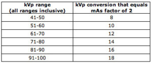 increasing the mAs value. If kVp values fall below the lowest available kVp setting then adjust the low kVp values upward while decreasing the mAs values to compensate. If some exposure times are excessively long and you are already using the highest available mA setting, lower exposure times can be achieved by selecting a faster receptor speed, using a lower ratio grid and by reducing the anode-film distance. The ultimate solution to excessively long exposure times is to purchase a machine with more mA.
If you are using a digital system, the latitude produces similar appearing radiographs at different exposure settings, but the image resolution with digital systems is directly related to exposure which is influenced by the signal to noise ratio. Resolution is lower at lower exposures and greater at higher exposures.